https://youtu.be/x-r7vncz4Ic
https://youtu.be/cI4Aq-M6-N8
Friday, May 6, 2016
Project 2 Part 2
Project 2 Part
2-Building Optimization
I am using part 3 simple to illustrate
the optimization process. Here is the requirement listed below.

Figure 1
2.2.1 Creating the
Conceptual Mass

Figure 2
Set out the inbetween space by using the formula 328 ft (the site width)- the width of the short building-the width of main building.

Figure 3
In the mass of the
campus parking is fixed, therefore I just create the extruded solid.

Figure 4
Monday, April 25, 2016
Arch 653_Project 2_30 St Mary Axe
1. Project 1 Update


In the Conceptual model, I created two
types of curtain wall system using the duplicate option under the curtain wall
1 panel to distinguish the colors of the curtain wall panel.

Figure 1
Here is a update Rendering:

Figure 2
2. Project_2 Using VISUAL PROGRAMMING: DYNAMO
First, because of complexity of the shape
and the curtain wall system, I simplified the curtain wall panel to make it
relatively flat, so it will simplify the problem in dynamo.
2.1 Adjusting RGB colors Manually

Figure 3
RGB stands for Red, Green and Blue, those
are the basic components to compose the colors. Link the two types of curtain
wall to the RGB colors are able changing the colors of the facade. Here is some
examples:

Figure 4

Figure 5
2. 1 Adjusting
Colors According to the sun

Figure 6
The color will display in different colors according
to the values of the angles of the sun and the normal of the facade panel. The
larger of the angle, the more green color will display on the panel. On the
contrary, the smaller of the angle, the more red color( making more purple)
will display on the panel.

Figure 7

Figure 8

Figure 9
Lastly, I want to thank to Professor Wei, who provides me with the great learning experience of Building Information Modeling.
Zepeng Jia 2016/4/25
Monday, March 21, 2016
Sunday, March 20, 2016
Arch 653_Project 1_30 St Mary Axe_Zepeng Jia
Arch 653_Project 1_30 St Mary Axe


1. Introduction
Location: UK, London
Architect: Foster and Partners
Structural Engineer: Arup
Construction Cost: €138 million
Floor Count: 41
Construction Date: 2001-2003

Figure 1
London’s first ecological tall building and an instantly
recognizable addition to the city’s skyline, this headquarters designed for
Swiss Re is rooted in a radical approach − technically, architecturally,
socially and spatially. Forty-one stores high, it provides 46,400 square
meters net of office space together with an arcade of shops and cafes accessed
from a newly created piazza. At the summit is a club room that offers a
spectacular 360-degree panorama across the capital.
2. Parametric Modeling Process
2.1 General Modeling Process:
1. Create a conceptual mass with parameters
2. Create a curtain wall panel system with parameters
3. Load the curtain wall system into the massing family
4. Load the massing family into the project which the floors and furniture are created
2.2 Creating Massing
After several attempts, I found out that it's better to separate the mass into two parts, one the the main mass, another one is the dome above the main massing.

Figure 2
Three reference circles have been create in the 1st floor, 17 floor and 40 floors with radius parameter on each circle which control the shape of the building.

Figure 3
The dome is formed by one vertical reference line, a half ellipse curve and the radius of 39th floor.

Figure 4
Dome radius and 39th floor radius shared a same parameter. As the result, as soon as the R changes, the dome and main massing are changed as well.
2.3 Creating Curtain Wall System

figure 5
Create curtain wall grid with the "divide surface" command

Figure 6

Figure 7
I created two adaptive panels and load into the main mass (figure 6) and the dome (figure 7). The main mass panel consists three parameters, the thickness of the glass, the width of the degrid and the height of the degrid. I load the panel into the massing family.
2.4 The result and Conclusion

Figure 8
All the parameters have been tested and it works well. However, the project have room for further development on the inner part of building.
3. Renderings

Figure 9
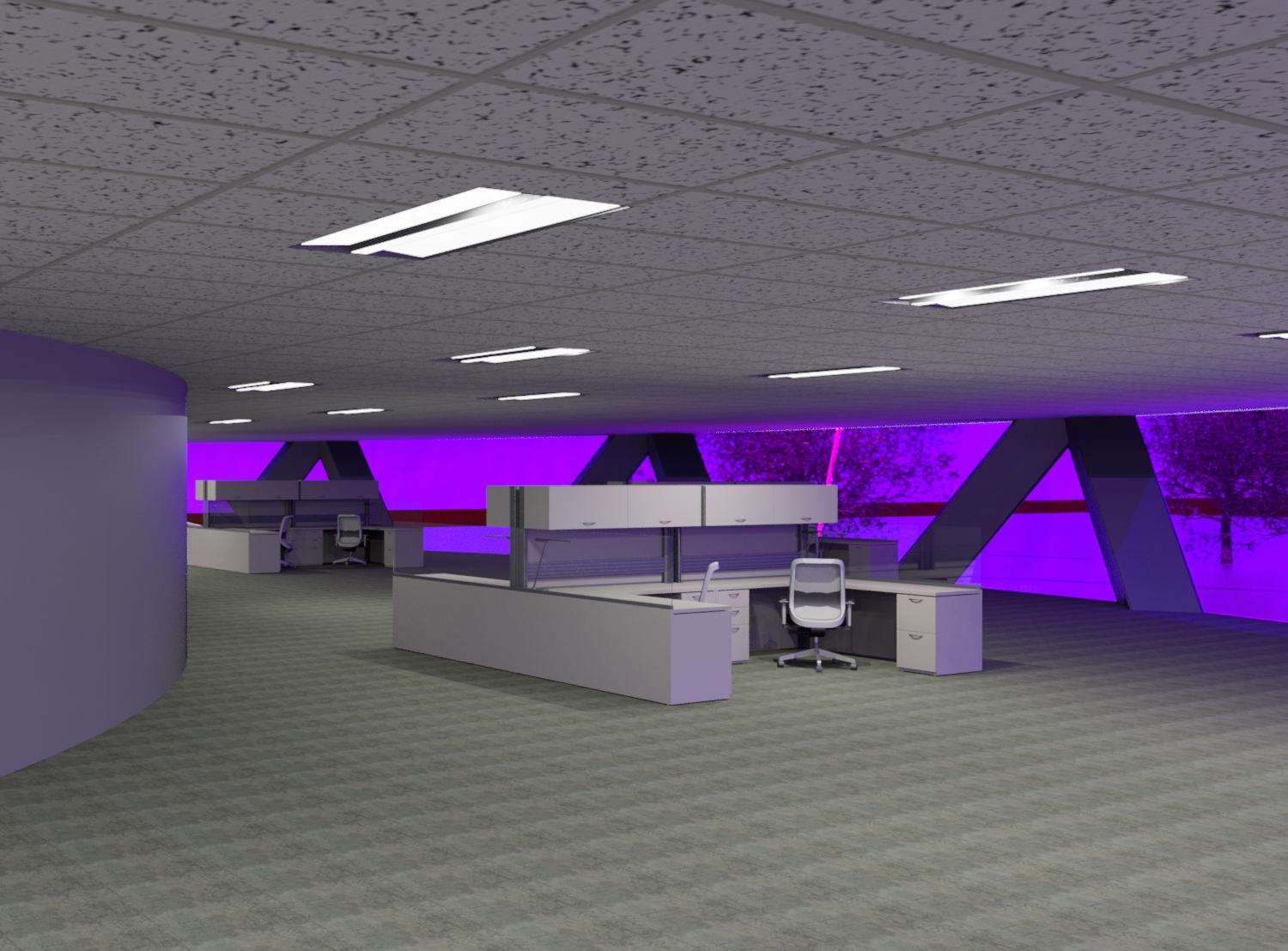
Figure 10
Subscribe to:
Comments (Atom)